3 Ways to Calibrate a Pressure Transmitter That You Can Easily Apply
During my learning days, when I hear a pressure transmitter (and other transmitters), it seems it is a very complicated instrument to calibrate (How about you?).
.
But when I already learned and experience calibrating it, I can say that it is just calibrating a simple pressure gauge. the only difference is that the applied pressure is now converted into a current output, the 4 to 20 mA signal. In order to be understood by the user, it will be converted back to pressure units by the PLC display.
.
We do not need to know how to operate a PLC (but it is better if we do), what we need is, during calibration, it is important that the operator of the PLC is with you, make the user operate while you perform the calibration.
.
This simple pressure transducer is a transmitter because it is used from a remote location going to a control panel (PLC) to monitor and control the process involving pressure. The signal is transmitted through a wire in the form of a current (the 4 to 20 mA signal).
.
In transmitter calibration, not just pressure transmitter, an additional knowledge about linear interpolation is needed to understand the conversion of current output to pressure units or other units or vice versa. I get to be confused about this conversion when I was newly exposed to this so I will include the conversion formula here (just in case you are confused too). Just read on.
.
In this post, I will present the Following:
- 3 ways to set up a pressure transmitter for calibration.
- Loop calibration set-up
- Individual or Isolated Instrument Setup
- Current Meter In-Series Connection Setup
- 3 types of pressure transmitter connector
- what standard to use in calibrating a pressure transmitter and how it is connected and configured
- The conversion of pressure to current using manual computation ( or by using a method called linear interpolation)
- Calibration procedure
.
3 Ways to SetUp a Pressure Transmitter for Calibration
Loop Calibration Setup
Loop calibration is a calibration setup where the instrument is calibrated as a whole involving the pressure sensor and transmitter inter-connected to the PLC display. It is a calibration where the instrument is being calibrated in its actual usage in a remote location from its display.
.
The advantage of this is that you are getting the overall performance of the instrument. you can determine the overall functionality of the loop.
.
The disadvantage is that if there is an error, you can not tell immediately what is causing it and troubleshooting may take longer.
.
Loop calibration involves a 4 to 20 mA signal. Readings can be taken as current units or pressure units. Current is the signal that is being sent to the PLC Display but it is converted back to pressure units.
.
If you want to get the current readings, you need to connect a multimeter that is in series with the wire going to the PLC.
See no. 3 set up below.
Below is the set up for loop calibration:
- Remove the installation of the pressure transmitter on its location. Do not remove cable or wiring connections.
- Using the proper fittings and connectors, connect the calibrator pressure output to the input of the instrument.
- See to it that there is no leak.
- Check and ensure correct tagging or ID in the PLC display to match with the transmitter in order to see the readings once pressure is applied.
- If you want to check the current value while applying pressure, you may do simultaneously the setup no 3. below.
- It is now ready for calibration.
Individual or Isolated Instrument Setup
In this setup, we will isolate the main instrument to other connections, only the main sensor that is directly tapped to our reference standard and reading is taken directly on the display of our references standard.
.
This method is more accurate because no other outside sources of error are present. Troubleshooting is easy, you can directly determine the problem because you are just concentrating on the instrument itself.
.
But the disadvantage is that mistakes may occur during the re-installation. So be careful not to interchange connections. Also, you need a special calibrator with a loop power to perform this.
.
Instrument-only calibration involves the output signal which is a directly displayed as 4 to 20 mA. You need to apply interpolation in order to determine or convert it to pressure value or units.
.
How to use interpolation or to convert pressure to current? Continue reading further…
.
Individual Instrument Calibration Setup
- Remove the instrument from its location including its connecting wires. Ensure there are no other power lines to be disturbed.
- Connect the calibrator supply pressure to its input or instrument sensor. This is the same as loop connection setup. But this time, the instrument is isolated.
- Since the connecting wires are removed, the output ports are exposed. Check the transmitter connection diagram or label to ensure proper functioning and output signal detection.
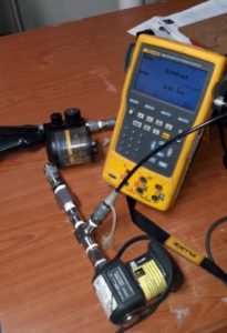
Pressure Transmitter output connection- Enable loop power of Fluke 754 for this procedure. - At the same time and connection, we can read the output current that is based on the supplied pressure.
- Through linear interpolation, we can determine the output in pressure units.
- Compare computed value on the displayed value if within the expected tolerances.
Current Meter In-Series Connection Setup
This setup is the easiest and most simple to perform. Just connect the Fluke 754 probe (or simply a calibrated multimeter) in series with the circuit or the transmitter current path and directly measure the actual current.
.
This procedure may not be a stand-alone or sufficient procedure, it is preferred to perform together with setup no 1, but if there is no other option and the user approves this procedure, then it may not be a problem.
.
This set up does not need any access or connection from the transmitter itself, only verifying the actual current then compute for the converted pressure value. The only thing you can measure is 0 pressure (4mA) and the actual pressure that is used in the process.
.
Some instruments have an easy access where you can directly tap the current meter to a dedicated current-output port to get the current reading.
The main standard used in Pressure Transmitter Calibration
I believe we are now familiar with FLuke 754 as a reference standard for pressure calibration

especially transmitters. There are other process calibrators out there but this is what I always use since I started calibrating. It has pressure modules that have different ranges depending on your needs.
If you have a lot of instruments involving pressure and temperature instruments, this calibrator is a must.
See the related article in this post about 11 Ways to use Fluke 754..
3 Types of Pressure Transmitter Fittings/Connector
Pressure transmitter has different connections and design depending on its use or purpose. Below are some types of pressure transmitter connectors that I encounter:
- Diaphragm type connections– mostly used in a pharmaceutical company. Used in a liquid which has a solid particle that can clog on a simple NPT connector. I always like calibrating this type of connector because you can easily remove and return the unit. But sometimes, you need a dedicated fitting in order to connect it to the calibrator. For us, we need to have it manually fabricated in order to use it.
Diaphragm Sensor and Fittings
- NPT type connector– the most common type of connectors being used for general purpose. This is a 1/2 size NPT which is what we usually encounter.
Pressure Transmitter with 1/2 NPT Fittings
- Vinyl Tube or Rubber Fittings for differential pressure– used for low-level pressures and mostly air is the medium used. As for its calibration, it is the same as a regular differential pressure gauge, just supply pressure to its positive side and let the negative side exposed to ambient. For more info about differential pressure calibration, visit my post here –Differential Pressure Gauge.
Using the loop power for transmitters with no power supplied to it.
By enabling this in fluke 754 ( or other process calibrators with the same capability), you can power up a transmitter and read the 4 to 20 mA output signal. No other connections or power supply needed.
Pressure Transmitter Calibration Procedure
- Inspect the UUC ( Unit Under Calibration) visually for any signs of damage (leakage or broken wires) and cleanliness issue. Record observations on your datasheet
- Connect the pressure transmitter on the pressure hose of the pressure module (use appropriate fittings). See to it that there is no leakage. Refer to the 3 ways setups above
- Allow proper stabilization of the UUC and the reference standard (at least 30 minutes).
- Prepare your measurement data sheet where the current to pressure conversion are listed. (See below on how to convert using interpolation)–What is a Measurement Data Sheet (MDS)? visit this link to learn more>>MDS
- Record five test points that are uniformly distributed on the range of the pressure transmitter, preferably 0%, 25%, 50% 75% and 100% of the range.
- Prepare the hydraulic pump ( or pneumatic pump if necessary). Close the Bleeder knob of the hand pump
- Do not apply pressure yet to the hand pump, this is the Zero pressure setting. Current value should be equal to 4 mA. Check the display on the Fluke 754.
- Take note of the measured value and record on your data sheet.
- Apply the next pressure range and record the equivalent current value.
- Continue until all ranges are completed.
- Repeat the procedures for the 2nd trials each range.
- Make sure that all readings are within tolerances provided.
- If adjustment is needed, make sure to read the instruction or service manual. methods of adjustments are different for every manufacturer.
Using Manual Computation or Linear Interpolation as a Method for Converting Different Output Units to Current.
There is a formula that we can easily use to convert most (or all) units utilizing 4 to 20 mA signal to mA units. There are others out there but this is the simplest I know.
Below is a simple formula for pressure to current conversion.
For example:
range is : 0 to 10 Bar
Full range = 10 Bar
Displayed or measured value: 7 Bar
15.2 mA is the equivalent current value of a 7 Bar pressure.
For Value or range which is not starting with zero ( with a vacuum range), use below linear interpolation formula.
You can also encode this to excel for easier conversion.
If you want to know and calculate the error, Just subtract the True value with your computed value.
Error = Measured Value – True Value
.
If the Pressure Transmitter has an accuracy of 0.5% of the range, then 0.005 x 7= +/-0.035 Bar, you can use this as the tolerance to determine a pass or fail results. Or you can ask the user for their respective tolerances.
Conclusion
Transmitters are very useful instruments in monitoring and controlling a process remotely. One of this is the pressure transmitter, like other transmitters, a pressure transmitter is also using a 4 to 20 mA signal which can be measured and converted into the desired unit. In this post, I have discussed and shown the 3 setups that I always performed during pressure transmitter calibration. I also presented the different connections and fittings that you may encounter during calibration. and lastly, I presented how to calculate and convert a pressure value to current value using a simple conversion formula.
.
Do you experience other setup and standards for calibrating a pressure transmitter? Comment below.
If you like my post please share and subscribe.
.
Your calibration friend,
Edwin


Comments
Post a Comment